
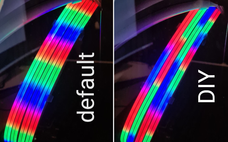
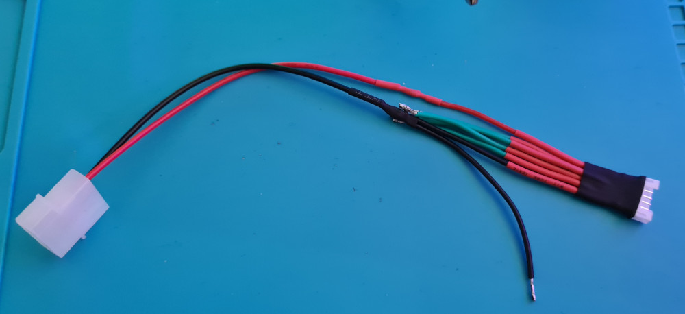
When I saw that Lian Li GPU Strimer Plus for the first time, I immediately wanted it and was pretty hyped when I saw it "in stock" and ordered it. As much as I was hyped, I was disappointed when I received and installed it using the included 5v 3pin ARGB adapter.
With that adapter the "108 addressable leds" will become 27 addressable leds ONLY as the adapter is acting like a splitter and just clones the signal of the first data line to the other three ones.
Only the Lian Li control box (that comes with the 24pin mobo Strimer Plus) is able to address all of those leds and ONLY with the built-in pre-made effects...well, unless we're creating our own controller!
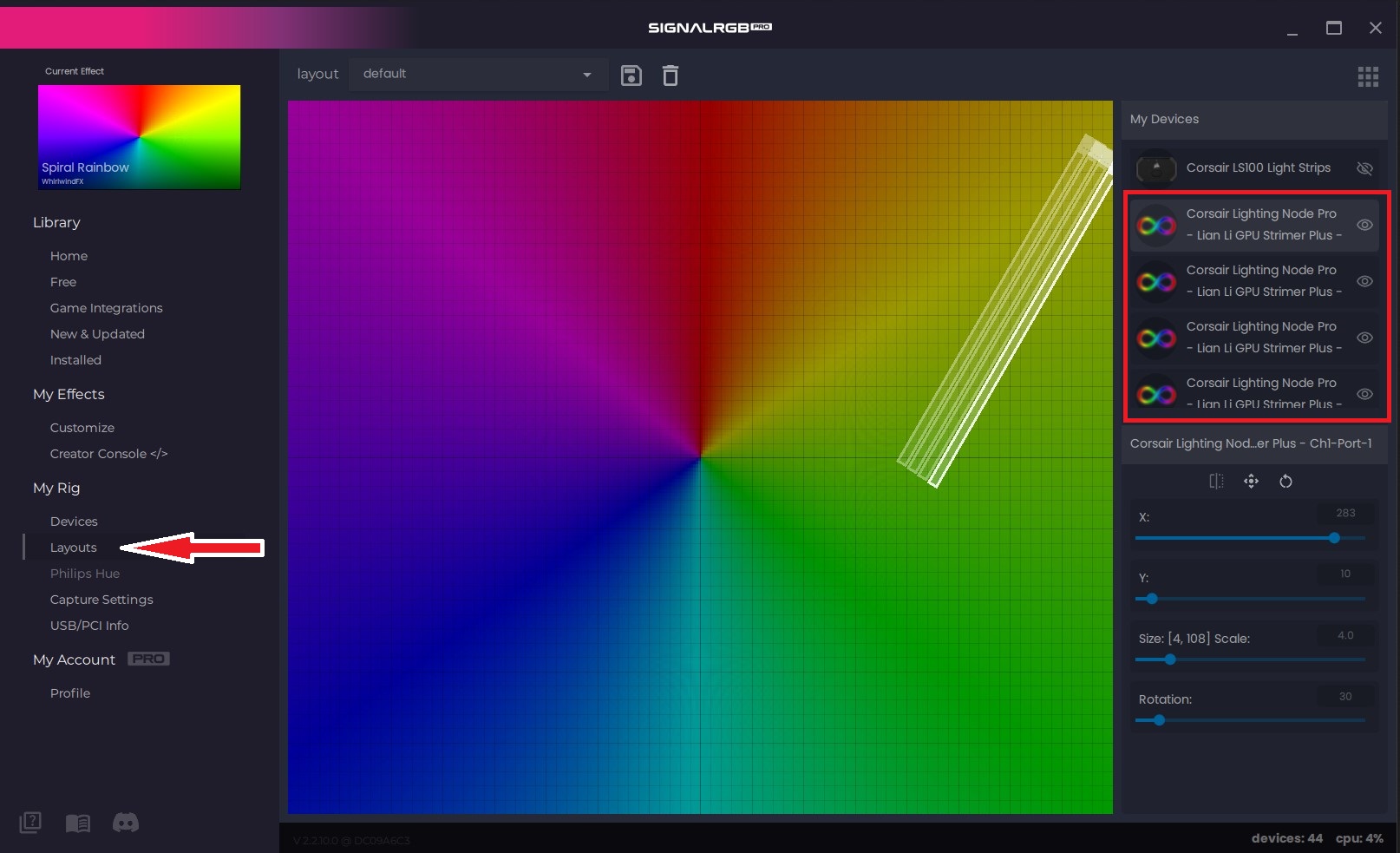
This is what this quick tutorial is about, make the Lian Li Strimer Plus fully addressable!
https://raw.githubusercontent.com/Legion2/CorsairLightingProtocolBoards/master/package_Legion2_CorsairLightingProtocolBoards_index.json
The Arduino IDE requires sketch files to be in a correctly named subfolder, so confirm the dialogue asking to move the file to the correct folder with "OK".
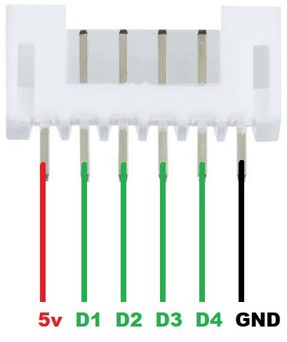
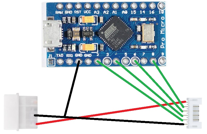
ch1|port1, ch1|port2, ch2|port1 and ch2|port2.
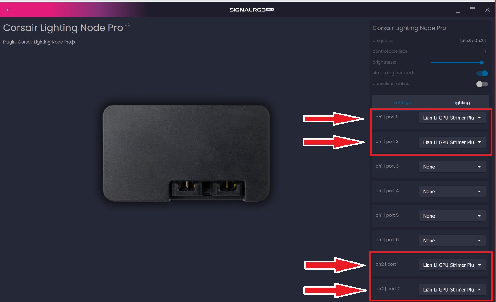
ch1|port1, ch1|port2, ch1|port3, ch2|port1, ch2|port2 and ch2|port3.ch1|port1, ch1|port2, ch1|port3, ch2|port1, ch2|port2 and ch2|port3.